

Ebook
Supercharge Your Excel Estimating with RIB CostX

When an innovative copying process was developed in the 1840s, the lines on newly printed drawings and maps had a distinctive blue tone that would earn them their nickname. Construction blueprints have now been with us for almost two centuries, and the term has taken on new meaning and significance as the industry has evolved.
In this blog post, we explore the origin of the construction blueprint and the basic elements and applications that still define them today. We also provide a list of tips that can help anyone read and interpret blueprints like a seasoned industry veteran.
Construction blueprints are two-dimensional drawings that contain all the details and information needed to complete a project. A set of blueprints typically includes information on design, dimensions, materials, and critical features for contractors and other stakeholders.
Traditional paper blueprints have gradually disappeared from construction sites and the offices of civil engineers, architects, and contractors, but the term is still used to describe standard drawing sets in paper or digital formats. While technology has made it easier to create and share blueprints with dispersed project teams, the same basic rules and conventions apply when it comes to reading these prints correctly.
The ingenious blueprint process was developed in 1842 by chemist John Herschel when he put translucent construction drawings in contact with a special type of paper. This blueprint paper is precoated with ammonium ferric citrate and other chemicals that allow images to be transferred when both the paper and original are exposed to the same intense light.
This simple process became the industry standard for communicating design information and project changes to busy construction sites, with the ability to reproduce large drawings quickly, providing benefits even modern photocopiers could not match.
Various types of blueprints have endured since they provide useful visual guides and comprehensive plans that all contractors, engineers, and architects need. The most current blueprint set becomes a single source of truth that prevents misunderstandings, errors, and delays on the job site. This information is now communicated faster than ever before, with computer technology eliminating the need for couriers who once hurried from offices to construction sites delivering the latest bundle of prints.
Well-organized blueprints also break the construction process into manageable steps to improve organization and planning. A hierarchical drawing set typically begins at the macro level (site and excavation plans) and drills down to floor plans, elevation plans, details, and specialty drawings. Digital document control systems help to organize blueprints in a logical manner or cross-reference with numerical filing systems like CSI MasterFormat.
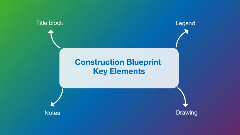
Anyone raised in the digital age might be unfamiliar with some of the formats, symbols, and notes found in a typical construction blueprint, but it is important to study and understand each of these key elements to prevent misunderstandings or omissions.
This often-overlooked corner of the blueprint contains essential information that should always be reviewed along with the rest of the information on the page. A typical title block includes the name of the designer or architect, the drawing scale, standard print size, revision, and sheet number (e.g. 1 of 10).
Most blueprints utilize various symbols and line types to represent specific features like windows, doors, appliances, and stairs. The drawing legend presents a summary of all symbols used and what they mean, making it easier to interpret the drawing quickly.
The drawing itself occupies most of the space on a typical construction blueprint. The level of detail presented varies depending on the type of construction drawing, with structural drawings dedicated to elements like beams, columns, and load-bearing walls, and perspective drawings presenting a less technically oriented visual overview.
The notes on a blueprint also contain important information that can be easily overlooked. Notes might include material specifications, installation methods, and safety procedures that won’t be found in the body of the drawing. They might also include references to other sheets that make it easier to follow the overall blueprint set.

Notes, drawings, legends, and other elements are only useful when you understand how to read construction blueprints and find the information you need quickly. This is a skill many construction professionals develop over the course of their careers, but a few basic tips and best practices help to accelerate the learning process.
The drawing scale, usually found within the title block or next to an individual detail, is one of the first things you should check when you read a blueprint. The scale is expressed as a proportion (1:10, 1:100, 1:1000, etc.) that indicates the size of the image relative to the actual building, view, or detail.
Reviewing the scale first helps to put all other dimensions, notes, and images into context as you interpret and utilize the rest of the information in the blueprint. Correct interpretation of the scale also prevents costly errors during the quantity takeoff, estimation, and building processes.
Most symbols used to represent common objects on a blueprint have been designed to resemble the actual item, but this is not always the case. Blueprint legends serve a valuable purpose by capturing and decoding all symbols for each sheet in one convenient place. The symbols used for electrical, plumbing, and other specialties can appear similar to one another, so it is important to study each legend carefully before proceeding.
Section views are useful components of construction blueprints but can also be difficult to visualize and understand. Section views use vertical cuts through the structure to reveal what would ordinarily be hidden inside. These views are extremely helpful when defining the inner composition of walls, foundations, or roofing structures. Reviewing a section view correctly requires an accurate interpretation of the cut location and line of sight (LOS).
Construction specifications are written documents that describe the scope and methods of work, along with relevant information on materials, workmanship, and permits for a specific project. While blueprints are primarily visual documents that convey the size, shape, and features of a building, construction specs are written documents that go into greater depth regarding installation, building codes, and safety standards. Reviewing blueprints and specifications side by side is the best way to ensure you have the most current and complete information at your disposal.
Building floor plans, site maps, and section views help to make up a complete construction blueprint set, but specialties like electrical, mechanical, and plumbing also utilize blueprints to document and communicate their layouts and design features.
Even contractors and subcontractors working outside of these specialties should review the unique symbols used in specialty blueprints. This understanding allows them to cross-reference floor plans and detect potential clashes or areas requiring additional coordination.
Various lines are used in construction blueprints to display different features and elements. Solid lines are usually used for walls, doors, and building outlines, while dashed lines indicate an object is hidden behind or within another wall or surface. The use of lines differs depending on the types of blueprints, so it is important to refer to the legend when lines are used to define drawing elements. For example, a solid line in a plumbing blueprint represents a sanitary water pipe, while a dotted line indicates a plumbing vent location.
Blueprints have evolved over the past two centuries, as have the software tools used to create, interpret, and utilize them. RIB CostX software enables automatic or manual quantity takeoffs from CAD files, scans, or even PDF files, for the efficient preparation of estimates, cost plans, tenders, and bills of quantities (BoQ).
CostX also identifies and tracks changes in blueprint revisions to maintain traceability and prevent errors. Built-in drawing comparison tools utilize overlays, line-by-line comparisons, and object tracking features to ensure no details are missed as blueprints are revised.
The old-fashioned blueline printers of the 19th and 20th centuries saved construction professionals countless hours by eliminating time-consuming tracing and hand-copying processes. This innovation was the first of many that would eventually lead the industry into the digital age. Building information modeling (BIM) and 3D CAD modeling have made blue lines and the scent of ammonia a thing of the past, as new software tools evolve to support the digital blueprints of the future.
RIB CostX is a cloud-based solution that bridges the gap between the past and future of blueprints, with accurate takeoff now possible from nearly any drawing or blueprint format. CostX also incorporates capabilities like embodied carbon calculations, subcontractor comparisons, and professional reports to support today’s ambitious and sustainable construction industry.
Get your free demo today, and discover the many ways RIB CostX can transform your business!


The United Arab Emirates (UAE) is home to some of the world’s most ambitious construction projects. From record-breaking skyscrapers to…

Disconnected workflows between estimation, design, and execution are a leading cause of cost overruns in construction projects. This challenge is…

Today, organizations need reliable access to data across the board. This is important for small businesses, but enterprises are even…