
28 October, 2025
10 mins read
10 mins read


Scale has always been an essential part of the architect’s (or artist’s) tool kit, since it allows them to present extremely large objects or structures on a single sheet of paper or computer terminal. The use of scale drawing in the construction industry is accompanied by some important rules and conventions that make these renderings easier to interpret.
In this blog post, we take a closer look at this important concept as we review different scales in drawings and how they are used. We also provide a list of tips and best practices that simplify the application of scale in the construction industry.
A scale drawing uses proportion to adapt the actual size of a building, map, or view into one that can be read and understood more easily on paper. Drawing features remain proportional relative to one other, but smaller (or larger) than the actual objects.
The construction industry is known for producing large buildings, bridges, roads, and infrastructure projects, and all these immense structures must be represented in drawings that clearly convey their size. For example, if a 20-meter building is drawn at a scale of 1:100, the building will appear to be just 20 centimeters tall on paper, while the width and other building elements remain proportional to the real-world structure.
The need for engineering drawing scale is obvious, with many of the world’s largest buildings covering an area of more than 1 million square meters. These structures would be impossible to design and build without scaled down models to make the drawings more manageable. When paper blueprints were the norm, a scale drawing set allowed all project information to be conveyed on standard C (18” x 24”) or D (24” x 36”) sized prints.
In today’s digital construction industry, scale drawings also support direct quantity takeoff from either 2D or 3D files, with the defined scale factored into automated bill of quantity (BOQ) calculations. The use of scale also provides a common language between various design and construction teams, with new items and features built to align precisely with the size and scale of existing elements.
Over time, standard conventions have evolved that link common construction drawing scales to various formats. Although you can learn how to scale a drawing using almost any proportion, these established norms allow both designers and reviewers to quickly understand the size and scope of a project.
The easiest scale to convey is really no scale at all, since 1:1 drawings retain the original size of the object. This choice is rare in the construction industry, except for the full-sized mockups sometimes used for architectural presentations. Even small details and finishes usually require some reduction of scale to make them more manageable.
A typical application of a 1:1 scale in other industries would be a label drawing intended to retain its full size when printed.
This scale is commonly used by construction architects as they create new floor plans and elevations to convey a sense of space and flow within a building. This scale convention is ideal for metric units. For example, a 10-meter beam is easily conveyed using a 10 cm drawing representation.
With proportions set 10 times smaller than a typical floor plan, the ‘bird eye’ 1:1000 and 1:1250 scales are ideal for location plans or key plans that depict entire communities or large commercial structures. Neighboring roads, easements, and green areas can be included without compromising the level of detail.
This happy medium scale is useful for the floor plans of small residential or commercial spaces. The zoomed in images allow designers to include more details, fixtures, and callouts that might not be practical using the 1:100 scale.
Although most drawings today are completed using 2D or 3D CAD software, the scale is still relevant when drawing files are printed out or included in reports and presentations, or when the electronic files are used to estimate material quantities and other construction project inputs.
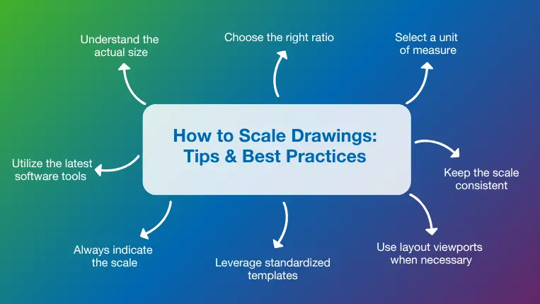
Deciding when and how to scale a drawing is a bit more complicated than it might seem. Following a few basic practices will allow you to utilize scale in a way that consistently makes drawings and engineering designs easy to interpret.
Before you can select the most appropriate scale for a drawing, you need to understand the actual size of the real-world object, area, or structure. A site map for a new development should include the entire area of interest, while showing as much detail as possible on printed or digital maps. In some instances, very small objects must be scaled up to 2:1, 4:1, or more to make fine details visible.
Selecting the ratio for a scale drawing requires an understanding of the actual size, as well as the common drawing scales used for each purpose. Established engineering and architectural scales help designers remain consistent as they create each drawing type. For example, architects following the Imperial scale will typically use 1:24 for building sections, while the SI (international) scale calls for a scale ratio of 1:20 or 1:50, depending on the size of the building.
Unit of measure (UOM) refers to the standard measurement unit used to measure or count items. While construction materials like lumber and tubing are usually measured in feet, yards, or meters, items like gravel and concrete are typically measured according to their weight or volume (cubic meter, cubic yard, etc.).
The unit of measure must be selected prior to setting the ratio, since the UOM establishes a reference point for the scale. Traditional land maps often include a scale bar to graphically depict how a distance of a mile, kilometer, or 100 kilometers will appear on the map.
The information conveyed on construction drawings feeds directly into real-world building, analysis, and quantity takeoff processes, so it is important to utilize the same engineering drawing scale throughout the drawing. Diverging from the scale can easily lead to costly errors and miscalculations, so any magnified details or features that must be included within the drawing should be clearly labeled.
One way to minimize interpretation issues on a scale drawing is by utilizing layout viewports. A viewport is essentially a “drawing within a drawing” that uses rectangular borders to segregate views and define the scale for each area independently. This technique is useful for construction drawings that must include both small and large elements to describe a building feature adequately. Viewports might also be used to show the same feature at different scales.
Designers and architects who regularly work with specific types of scale drawings save themselves time and effort by creating standard templates with predefined scales and title blocks. Advanced CAD software uses the insertion scale associated with the template to automatically size each object or view appropriately.
The use of scale has become less topical in recent years, with 3D models allowing us to zoom in and out at will, and no traditional paper formats dictating a preset drawing ratio. Despite these advancements, every construction drawing, even those presented in reports or presentations, should define the scale clearly so that all stakeholders understand the project size and design intent.
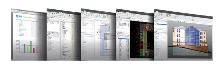
Advanced drawing and design tools like CAD software and building information modeling (BIM) simplify scale drawing by building the geometry and other component details directly into the model. Construction drawing views at specific scales are automatically generated by the software. Advanced estimation and BIM takeoff software complements these digital design tools by pulling precise quantity and cost information directly from intelligent models.
As the construction industry moves into the digital age, scale drawing remains a fundamental concept. Blueprints that once captured entire building designs on paper have given way to 3D models that bring them to life on computer screens, but the importance of scale remains unchanged. Construction software helps teams leverage the benefits of scale drawing while avoiding pitfalls.
Powerful solutions like RIB CostX interpret predefined scales to enable fast quantity takeoff from all commonly encountered 2D and 3D design formats, calculating areas, lengths, and counts with a single click. Estimates are easily updated based on the latest design to eliminate errors and provide a detailed audit trail for project managers.
Get your free demo today and discover how RIB CostX can transform your business!

Ebook