
Ebook
RIB CostX eBook – The Ultimate Estimating Solution


Structural engineering is crucial in ensuring construction projects are built with safety, quality, and compliance with industry standards. In this sense, a well-thought-out structural design plan is fundamental to achieving those goals. Drawings are crucial elements of a successful structural design process. These invaluable documents offer instructions about how the structure should be constructed, ensuring every stakeholder is on the same page.
In this blog post, we’ll discuss the details of structural drawings, describe their purpose and main types, and offer some tips on how to read them successfully.
Let’s dive in!
Structural drawings, aka structural plans or blueprints, are design documents that show how a structure should be built. They outline the dimensions and resource requirements for the load-carrying elements of a building, ensuring they are safe, resistant, and durable.
Structural plans are prepared by a licensed engineer during the design phase of a project. They must be signed and stamped by them to be considered valid for construction. The plans include detailed information about the project’s structural elements, such as beams, columns, slabs, walls, and foundations, as well as the dimensions, materials, reinforcement layouts, and connections required for these components.
These powerful documents are fundamental to the success of construction projects. They provide instructions for how the structure should be built with safety at the forefront. They also serve as powerful communication tools between architects, engineers, and contractors, ensuring complex structural information can be interpreted correctly to avoid costly reworks or safety hazards.
In the past, these documents were hand-drawn, which was very time-consuming and prone to error. While some engineers still use the traditional method, most have switched to digital technologies, like BIM management software, as a faster and much more efficient way to generate and work with drawings.
Structural engineeriing drawings contain robust information about a project in a visual format but also in a structured written format. The elements that compose them include:
There are several types of construction drawings, each serving a different purpose. Understanding the differences can help avoid confusion.
As mentioned, structural drawings focus on the strength and stability of the building, ensuring it meets the highest standards of quality and safety and complies with industry regulations. Architectural drawings, on the other hand, focus on the aesthetic and functional elements of the building, focusing on appearance and functionality. Lastly, as-built drawings are finalized versions of the project, reflecting all the changes made during the construction phase. They are invaluable for maintenance, renovations, or audits.
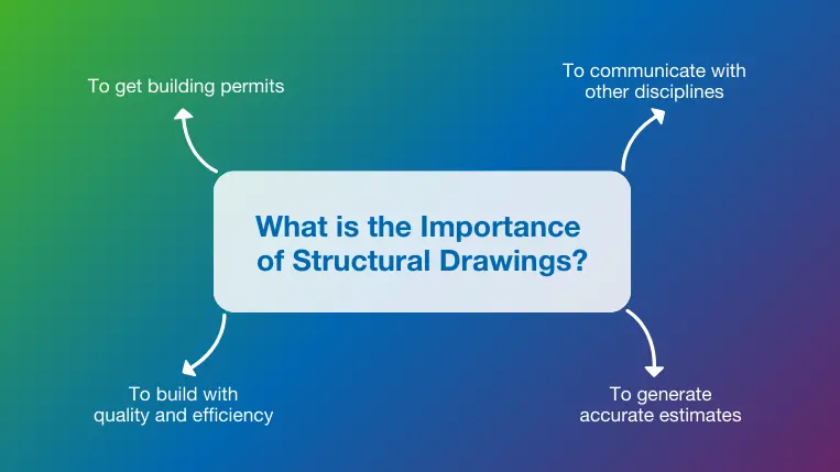
As mentioned above, structural drawings are fundamental tools to ensure the design team’s intent is effectively transmitted to the building team. Structural engineers must ensure these documents are understandable and accurate to facilitate their interpretation and execution at the building site. This is just one of the many reasons why they are so important, other reasons include:
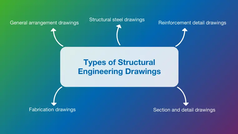
General arrangement drawings are the backbone of any construction project. They provide a detailed overview of the layout and dimensions of the structure, showing the spatial relationship and positions of the different structural components, like beams, columns, walls, and others, to show how they all fit together. GA drawings show the model from the most suitable position, including plans, elevations, and sections, to give a three-dimensional view of the structure and clearly understand the scope of work.
GA drawings are fundamental during the preconstruction planning stage. Their detailed information ensures that all stakeholders are on the same page regarding the project’s requirements. They also help secure permits to allow construction to begin.
As their name suggests, steel structure drawings focus on the design, arrangement, and connections of steel components within a structure, including beams, columns, trusses, braces, and others. Like GA drawings, these types of structural blueprints provide plans, elevations, and sections that help architects, builders, and other stakeholders clearly understand the spatial relationships of the different steel elements. They also offer additional details about connection points and instructions for materials, coatings, and treatments required for durability and performance.
These documents are invaluable tools for facilitating and streamlining the fabrication and assembly of steel components. They ensure no mistakes are made, and the structure’s safety and functional requirements are met.
In construction, almost all concrete structures are reinforced using reinforcement bars, known as rebars. To ensure the reinforcement work is done correctly, engineers generate reinforcement drawings detailing the bar spacing, lap lengths, bending shapes, and anchorage details for elements like beams, columns, slabs, and foundations. Like other drawings on this list, reinforcement drawings are fundamental to reducing errors during construction and ensuring the expected quality levels are achieved.
Section and detail plans provide in-depth views of specific areas or components of the structure, offering additional clarity not found in general arrangement plans. They also provide details about an element’s internal structure, including information about materials, dimensions, reinforcement placement, and layers within the component.
These drawings are fundamental to avoiding and solving challenges at the building phase, ensuring builders know how to carry out complex tasks while ensuring compliance with design and regulatory requirements. They are also invaluable tools for construction quality control, as the granular view helps to easily verify that the work is compliant.
Fabrication drawings complement structural steel drawings by offering a zoomed-in view of specific elements and parts of the steel structure. These drawings are usually generated for manufacturers to facilitate the fabrication of different steel components. They provide information about dimensions, materials, welding details, hole placements, and assembly instructions to ensure the final product is produced as expected. They are invaluable documents for prefabricated elements that are manufactured in a shop and transported to the site, streamlining the production process, reducing waste, and reducing fabrication time.
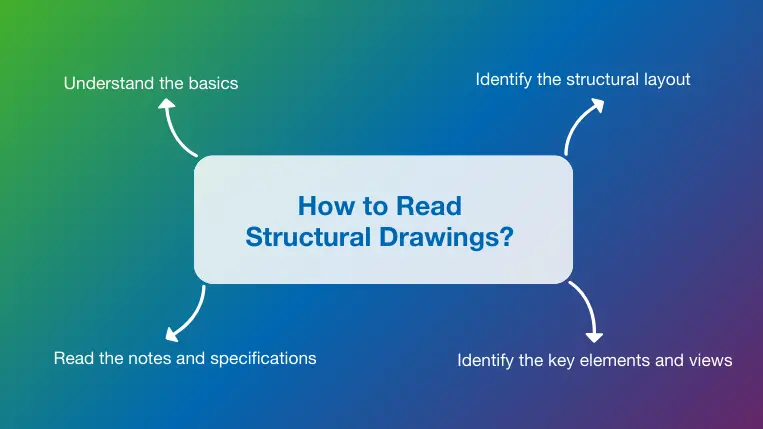
Structural engineering drawings are essential to construction projects. However, decoding them can be a challenging task, especially when projects are large and complex. Below are a few tips that will help you successfully interpret them.
The steps mentioned above ensure you go from a general to a detailed view of the drawing, helping you understand how the different elements relate to each other and what resources and methods must be used to bring the structure to life as planned by the structural engineer.
As you learned throughout this post, structural plans are fundamental documents that guide the construction process. They prevent errors due to miscommunication and ensure the expected levels of quality, safety, and regulatory compliance are met.
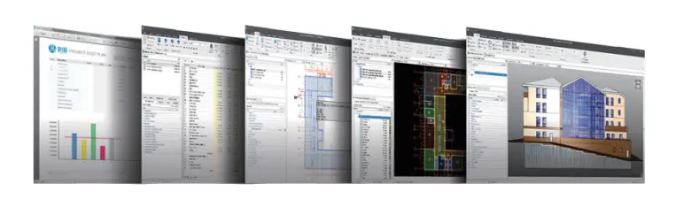
Modern construction software like RIB CostX ensures drawings can be visualized and easily shared without accessing complex environments like CAD software, which often segregates non-technical users. Our estimating and 3D takeoff solution supports a seamless transfer of data between all project stakeholders by supporting a range of file formats, including CAD files, 2D PDF, and 3D object-based DWF™, DWFx™, and IFC BIM models, allowing anyone with access to extract quantities, costs, and other relevant information directly from the drawings. Thanks to innovative technology, CostX uses the inherent intelligence embedded in each format, boosting decision-making and skyrocketing success.
This, paired with a range of powerful features like automation, BIM support, real-time progress reporting, financial control, and much more, makes CostX the best solution for streamlining the estimating process while ensuring a smooth project execution from start to finish. If you want to experience these benefits yourself, get your free demo for RIB CostX today!
Get My Free RIB CostX Demo Now

The United Arab Emirates (UAE) is home to some of the world’s most ambitious construction projects. From record-breaking skyscrapers to…

Disconnected workflows between estimation, design, and execution are a leading cause of cost overruns in construction projects. This challenge is…

Today, organizations need reliable access to data across the board. This is important for small businesses, but enterprises are even…